|
|
|
|
|
|
Modulation Aided Recording On Magnetic Tape
|
|
|
|
Select Channel Instead of Changing Cassette |
|
|
|
Patent application no. - 395/BOM/96 |
|
|
|
MAGNETIC TAPE RECORDER – PLAYER TO RECORD AND RETRIEVE MULTIPLE
MODULATED ELECTRICAL SIGNALS ON MAGNETIC TAPE. |
|
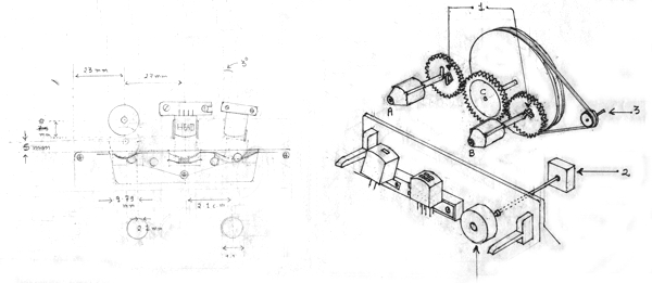
Raw image of pencil drawing of Magnetic Tape Recording / playing
mechanism
|
|
This
invention relates to recording of information on magnetic tape and
retrieving the recorded information from magnetic tape. Present
method of recording information on magnetic tape is; The information
is converted into an electrical signal. The electrical signal is
amplified and then fed to magnetic writing head that converts the
electrical signal into magnetic field corresponding to the
electrical signal. These tiny magnetic fields are stored on a tape
coated with magnetic material. Passing the magnetic tape over
reading head retrieves the information. The tiny magnetic fields
recorded on the tape create corresponding electrical signal in the
coil of the reading head. This electrical signal is amplified and
fed to output device like loudspeaker to reproduce the information
recorded on the magnetic tape. |
|
Invention (What is New) |
|
|
|
Recording
The invention is recording more than one information signals on a
magnetic tape. The information signals are converted into electrical
signals and are used as modulating signals to modulate carrier
signals of higher frequencies. More than one carrier signals are
modulated by different information signals. Each information signal
modulates one carrier signal.
All the modulated carrier signals are recorded simultaneously on a
magnetic tape. The signal recorded on magnetic tape is resultant of
mixture of all carrier signals.
Retrieving
Information
is retrieved by reading the information on magnetic tape by magnetic
reading head. Signal red by this head is resultant signal mixture of
all carrier signals recorded on the tape.
Selecting
An adjustable tuning circuit filters carrier signals and passes only
carrier signal it is tuned to. The selected carrier signal is
amplified and demodulated to obtain the modulating information
signal.
This recording and retrieving is done by one of the two types of
modulation. (Frequency Modulation and Amplitude Modulation)
|
|
|
|
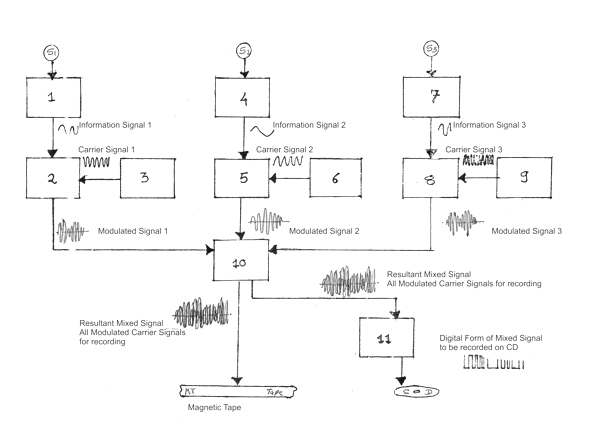 |
In above diagram, S1, S2, S3 are signal generators, like microphones;
each source provides one information signal in electrical form that
is to be recorded on magnetic tape.
Blocks 1, 4, and 7 are information signal amplifiers. Output of each
amplifier is fed to separate electrical signal modulators.
Blocks 2, 5, and 8 are electrical signal modulators. Each signal
modulator modulates the carrier signal fed to it by using
information signal as a modulating signal. All modulators modulate
carrier signals of different frequencies.
Blocks 3, 6, and 9 are carrier signal generators. Each carrier
signal generator generates one carrier signal of specific frequency
that is fixed for each generator and each carrier signal is fed to
one modulator for modulating the carrier signal. The output signals
of modulators are carrier signals, each of different frequency and
each modulated by different information signal. At this stage there
are more than one carrier signals each of different frequency and
each modulated by different information signal.
The output signals of signal modulators are fed to block 10 that
amplifies the signals. Output of block 10 is resultant signal of
mixture of more all modulated carrier signals. Output of block 10 is
recorded on magnetic tape by a magnetic tape writing head. |
|
|
|
Block diagram for retrieving the signal
|
|
|
|
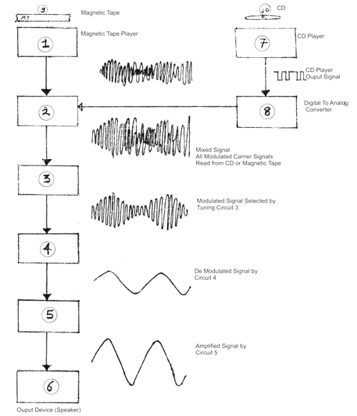
Block 1 is a reading device (playback head for reading magnetic
tape)
Block 2 is an amplifier that amplifies electrical signal retrieved
by the reading head. The retrieved electrical signal is resultant of
mixture of all carrier signals that are recorded on the tape, each
carrier is modulated by one information signal that was recorded on
the magnetic tape.
Block 3 is an adjustable tuning circuit (Same circuit that is used
in radio receiver to select one broadcasting station transmitted at
specific frequency). The tuning circuit selects one carrier signal
of specified frequency for which it is tuned by the user. All other
signals are suppressed, except one signal of specified frequency to
which the adjustable tuning circuit is tuned.
The selected carrier signal is amplified and demodulated in block 4.
Block 4 is a demodulating circuit that demodulates the selected
carrier signal to obtain the modulating signal. (Demodulating
circuit is same circuit that is used in radio receiver to demodulate
signal of the frequency selected by the user)
Output of block 4 is an original modulating signal that was used to
modulate the selected carrier signal at the time of recording it on
magnetic tape. The obtained signal is the information in the form of
electrical signal.
Block 5 is a signal amplifier that amplifies output of block 4.
Output of block 5 is the original information signal. This signal is
fed to output devices for reproduction (block 6). |
 |
|
|
|
|
|