|
|
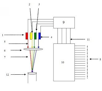
In above diagram, 8 is input 16 bit number to be transmitted fed to
processing circuit 10. This sends data to 9, which controls input
voltages to individual lasers depending upon input number. The
lasers are then collimated in to single beam using optical lenses
and transmitted through optical fibre
The transmitter consists of four lasers. Each laser is of specific
wavelength. The wavelengths (colors) (For Example
RED, YELLOW, GREEN and
BLUE). All four lasers are variable intensity lasers. The intensities
of these lasers are controlled by voltage input to laser sources.
Each source has an independent voltage input. The voltage input is
provided by an input voltage controller circuit. The circuit
generates separate voltage input for each laser depending upon
hexadecimal number to be transmitted.
Sixteen bit binary data is converted into equivalent 4-digit
hexadecimal number. Most significant digit of hexadecimal number
controls input voltage of RED laser source. The second most
significant digit of hexadecimal number controls input voltage of
YELLOW laser source. The third most significant digit of hexadecimal
number controls input voltage of GREEN laser source. And the least
significant digit of hexadecimal number controls input voltage of
BLUE laser source.
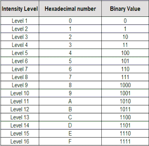
Sixteen hexadecimal numbers (0, 1, 2, 3, 4, 5, 6, 7, 8, 9, A, B, C,
D, E, and F) are assigned to 16 intensity levels of each laser.
The intensities of these laser change at every clock pulse in
accordance to hexadecimal number to be transmitted. All lasers are
transmitted through single optical fibre.
|
|
|
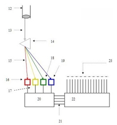
The receiver consists of a prism. The optical signal (light)
received is made incident on the prism. The prism divides
the light in to different components depending upon the
wavelengths. Each color component is made incident on
separate light sensor. The sensor generates electrical
signal in proportion to the intensity of light incident on
it. The sensor that senses intensity of RED light component
generates electrical signal whose voltage is proportional to
intensity of RED laser. Similarly for sensors those sense
intensities of YELLOW, GREEN and BLUE components generate
electrical signals proportional to intensities of respective
components incident on the sensors. Electrical signal
generated by RED sensor represents most significant digit of
four-digit hexadecimal number received in optical form.
Similarly the electrical signals generated by YELLOW, GREEN
and BLUE sensors represent second most, third most and least
significant digits of the four digit hexadecimal number
respectively. The outputs of all sensors are connected to a
circuit that converts electrical signals into equivalent
hexadecimal number. The four hexadecimal numbers together
represent a 4-digit hexadecimal number received in optical
form. The hexadecimal number is converted in to equivalent
16-bit binary number by hexadecimal to binary converter
circuit. The 16-bit binary number obtained after conversion
is 16-bit binary number transmitted by the transmitter. This
16-bit binary number is transmitted in one clock pulse time
in optical form through single optical fibre.
Four lasers transmit a 4-digit hexadecimal number. The
equivalent binary number transmitted at one clock pulse is
16-bit binary number. (16 bit binary number is equal to 2
bytes)
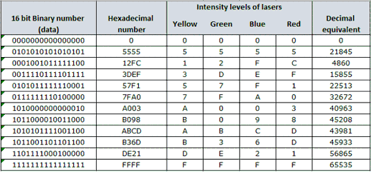
A table below shows some 16-bit binary numbers, their equivalent
hexadecimal number and corresponding combination of intensity levels
of lasers (RED, YELLOW, GREEN and BLUE
lasers).
|


